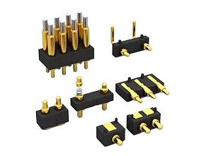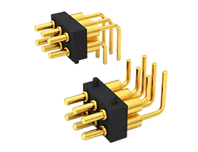


Choosing a high current pogo pin requires more than checking the maximum amperage in a datasheet. Engineers must also evaluate contact resistance, allowable temperature rise, working stroke, mounting method, duty cycle and heat dissipation. The correct choice is the spring-loaded contact that carries the required current reliably under the actual mechanical and environmental conditions of the application.
What Is a High Current Pogo Pin and When Is It Needed?
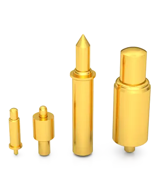
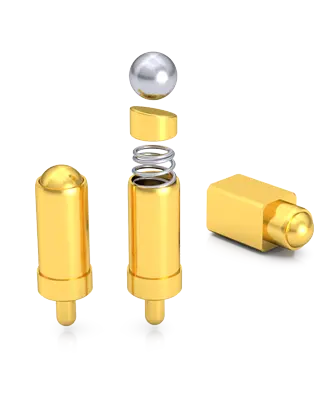
A high current pogo pin is a spring-loaded electrical contact designed with a conductive plunger, barrel, spring and contact interface capable of carrying more current than a conventional signal pin. It is commonly used where a removable, compact or repeatedly cycled connection must transfer power.
Typical applications include:
Charging docks for handheld and wearable devices
Battery modules and battery test fixtures
Industrial equipment and control systems
Medical devices and portable diagnostic equipment
Robotics, drones and automated production systems
Consumer electronics with detachable power interfaces
In practical sourcing, the phrase pogo pin high current should not be treated as a complete specification. Two pins with the same advertised current rating may perform differently because of their materials, dimensions, plating, spring force, mounting structure and test conditions.
How Much Current Can a Pogo Pin Carry?
There is no universal current capacity for every pogo pin. The maximum current must be confirmed from the supplier’s test data for the exact part number. Depending on the diameter and internal structure, high current pogo pins may be designed for power transfer ranging from a few amperes to substantially higher application-specific loads.
The datasheet rating should be evaluated together with the following conditions:
Continuous current: the current carried for an extended period
Peak current: a short-duration current during startup, charging or load switching
Duty cycle: the percentage of time during which current flows
Ambient temperature: the starting temperature around the connector
Number of active contacts: whether one pin or several pins share the load
Cooling conditions: airflow, PCB copper area, housing material and nearby heat sources
The maximum value in a datasheet should not automatically become the normal operating target. A suitable safety margin is necessary for contact aging, contamination, assembly variation and changes in ambient temperature. The required margin should be determined through application-level testing rather than a fixed percentage used for every design.
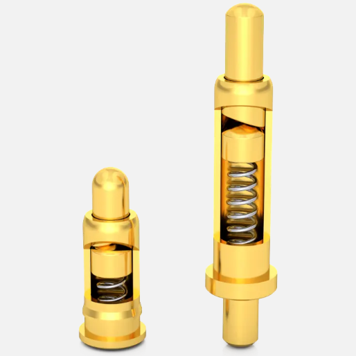
Contact Resistance, Temperature Rise and Current Derating
Contact resistance is one of the most important parameters in a power connection. It includes resistance within the pin as well as resistance at the mating interface. When current passes through the contact, power is converted into heat according to:
Power loss = Current² × Resistance (P = I²R)
Because current is squared in this equation, a small increase in current can create a much larger increase in heat. Contact resistance may also rise after repeated compression cycles, plating wear, dust exposure, oxidation or insufficient working stroke.
Temperature-rise testing should therefore be performed with the complete assembly, not only an isolated pin. The test should reproduce the intended current, compression, enclosure, PCB layout, cable size and ambient temperature. Measurements should be taken after the system approaches thermal stability.
| Design Factor | Effect on Electrical Performance | What to Verify |
| Higher contact resistance | Increases voltage drop and heat generation | Initial and post-cycle resistance |
| Insufficient compression | May produce unstable contact and intermittent power | Working stroke and assembly tolerance |
| High ambient temperature | Reduces available thermal margin | Worst-case operating environment |
| Repeated mating cycles | Can wear the plating and alter resistance | Life-cycle test at the specified stroke |
| Contaminated contact surface | May increase resistance or cause unstable contact | Environmental sealing and cleaning requirements |
Current derating may be necessary when several power contacts are placed close together, when airflow is limited or when the system operates near its maximum ambient temperature. The acceptable temperature rise must be defined according to the nearby plastic, PCB, battery and enclosure limits.
SMD vs THT Mounting and Multi-Pin Parallel Design
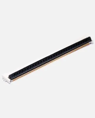
The mounting method affects assembly, mechanical strength, PCB space and heat transfer. Surface-mount designs work well for automated production and compact layouts. An smd pogo pin can be placed during SMT assembly, but its solder pad, paste volume, reflow profile and resistance to side loading must be reviewed carefully.
Through-hole or THT pins extend into plated PCB holes. They generally offer stronger mechanical retention and can be suitable for connectors exposed to repeated impact or lateral force. However, they require PCB hole allocation and may add assembly steps.
| Mounting Option | Main Advantages | Key Design Concerns |
| SMD | Compact layout and automated placement | Pad size, solder joint strength and coplanarity |
| THT/DIP | Strong PCB retention | Hole tolerance, solder fill and board space |
| Wire or cable termination | Flexible placement away from the PCB | Wire gauge, joint resistance and strain relief |
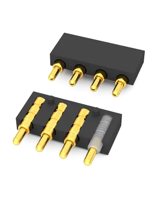
Multiple pogo pins can be connected in parallel when one contact cannot safely carry the required load. However, current may not divide equally because of differences in contact resistance, compression, trace length and solder quality. The total allowable current should not be calculated by simply multiplying one pin’s maximum rating by the number of pins.
Parallel power contacts should use symmetrical PCB traces, similar compression conditions and sufficient spacing for heat dissipation. Where practical, testing should measure the current and temperature of each contact rather than only the connector’s total current.
High Current Pogo Pin Selection Checklist by Application
Begin with the electrical load, but complete the selection using both electrical and mechanical requirements. A reliable pogo pin design should account for the entire tolerance stack between the PCB, housing, mating pad and compressed pin.
Define the load: specify continuous current, peak current, peak duration and duty cycle.
Set resistance requirements: confirm initial contact resistance and the permitted value after life-cycle testing.
Define the thermal limits: provide the maximum ambient temperature and allowable temperature rise.
Select the mounting method: compare SMD, THT and cable-mounted structures based on assembly and mechanical load.
Confirm the stroke: distinguish total travel, recommended working stroke and maximum compression.
Review the mating surface: define pad material, plating, flatness, cleanliness and alignment tolerance.
Consider the environment: identify vibration, shock, humidity, dust, corrosion and sealing requirements.
Validate service life: test resistance and spring performance after the required number of compression cycles.
For a faster technical evaluation, an RFQ should include the target current, voltage, mounting method, available installation space, working height, stroke, spring force, mating-cycle requirement, operating temperature, application environment and estimated order quantity. Drawings of the PCB and mating structure are especially helpful for customized designs.
FAQs About High Current Pogo Pins
Can I use the maximum rated current continuously?
Not without confirming the supplier’s test conditions. Continuous use depends on contact resistance, ambient temperature, compression, cooling and the thermal limits of the complete assembly. Application-level temperature-rise testing is recommended.
Does a lower contact resistance always mean a better pogo pin?
Lower and more stable resistance generally reduces voltage loss and heat, but it is not the only selection criterion. Working stroke, plating durability, spring force, alignment and mounting strength also affect reliability.
Can several pogo pins be connected in parallel for more current?
Yes, but the current may not divide evenly. PCB routing, contact resistance and compression should be balanced, and the parallel assembly should be tested under the maximum intended load.
Which mounting method is better for high current applications?
SMD is suitable for compact automated assembly, while THT often provides stronger mechanical retention. The better option depends on PCB space, production method, expected side load and thermal design.
What information is required for a custom high current pogo pin?
Provide continuous and peak current, voltage, dimensional limits, compressed height, required stroke, spring force, mounting method, mating-cycle target, operating environment and order quantity. Supplying PCB or housing drawings can reduce design revisions.